Master CFD From Scratch Using Free And OpenTools
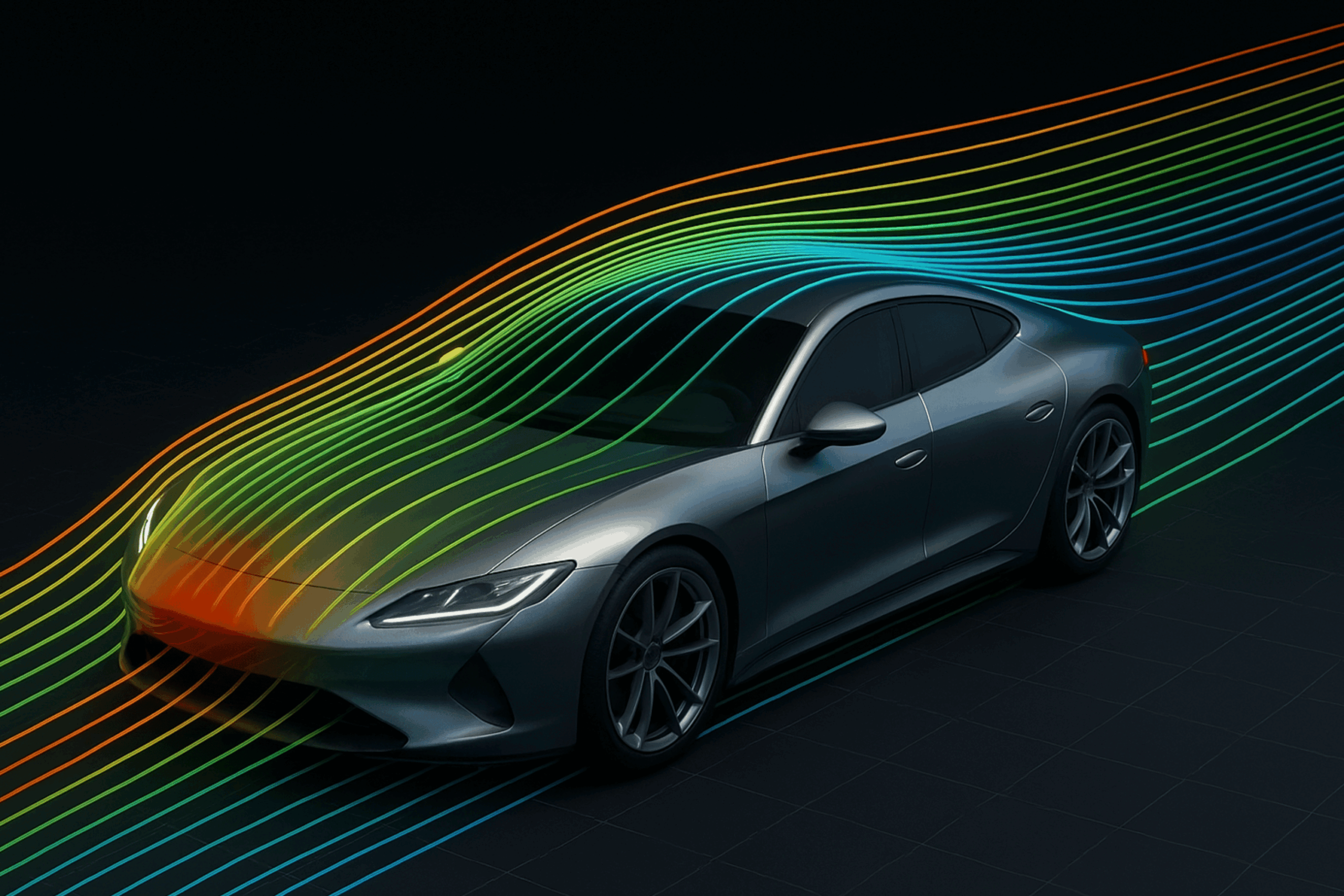
In the world of engineering and design, fluid dynamics plays a crucial role in shaping how objects interact with air and water. Whether it’s improving the aerodynamics of a car, enhancing the efficiency of a wind turbine, or predicting flow behavior in complex systems — CFD (Computational Fluid Dynamics) enables engineers to visualize and analyze these interactions before building physical prototypes.
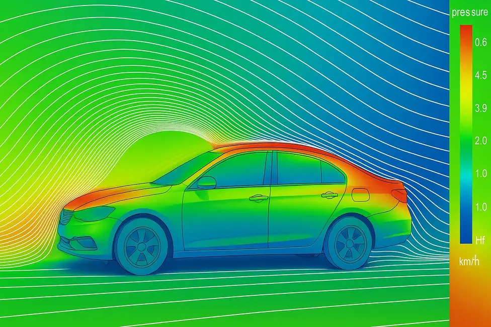
With CFD, we can simulate airflow, pressure distribution, and turbulence patterns — leading to smarter designs, reduced testing costs, and faster innovation cycles.
Step 1: CAD Modelling — Designing the Geometry
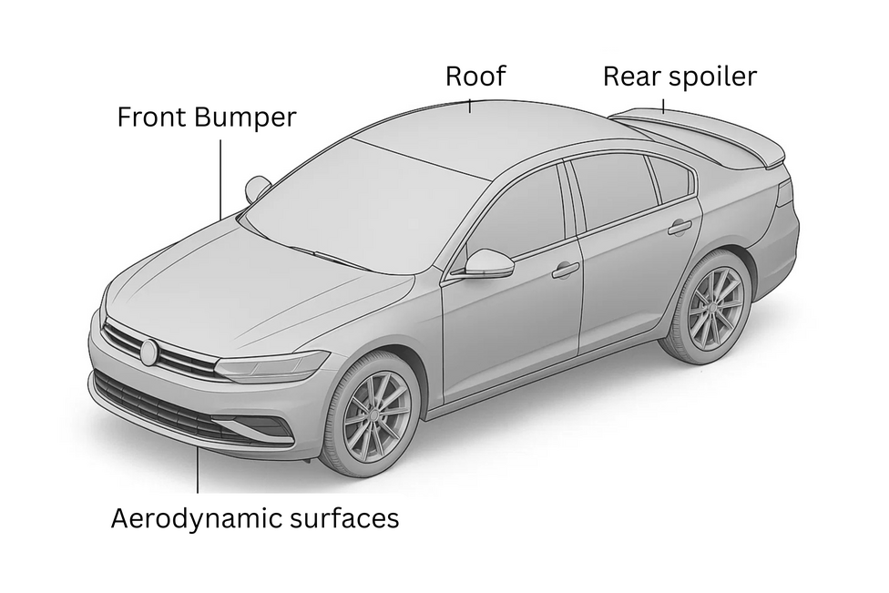
Every CFD project begins with defining the geometry of the system under study. This process, known as Computer-Aided Design (CAD), involves creating a virtual model of the physical object — be it an aircraft wing, a valve, or a car.
The goal at this stage is to create a clean, watertight, and simplified 3D model that captures all the essential physical features while removing unnecessary complexity.
A well-prepared CAD model ensures that later stages — such as meshing and simulation — proceed smoothly and accurately.
Step 2: Mesh Generation — Dividing the Geometry into Elements
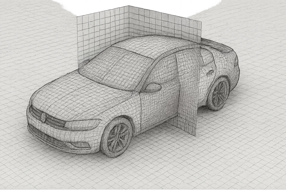
Once the model is complete, the next step is meshing — the process of dividing the domain into tiny cells or elements. The accuracy and stability of a CFD simulation heavily depend on mesh quality.
A finer mesh in critical regions (like near walls or around curves) allows for capturing detailed flow behavior, while coarser meshes elsewhere save computational time.
The mesh acts as the numerical backbone of the simulation, determining how equations are solved across the geometry.
Step 3: CFD Solver — Solving the Physics
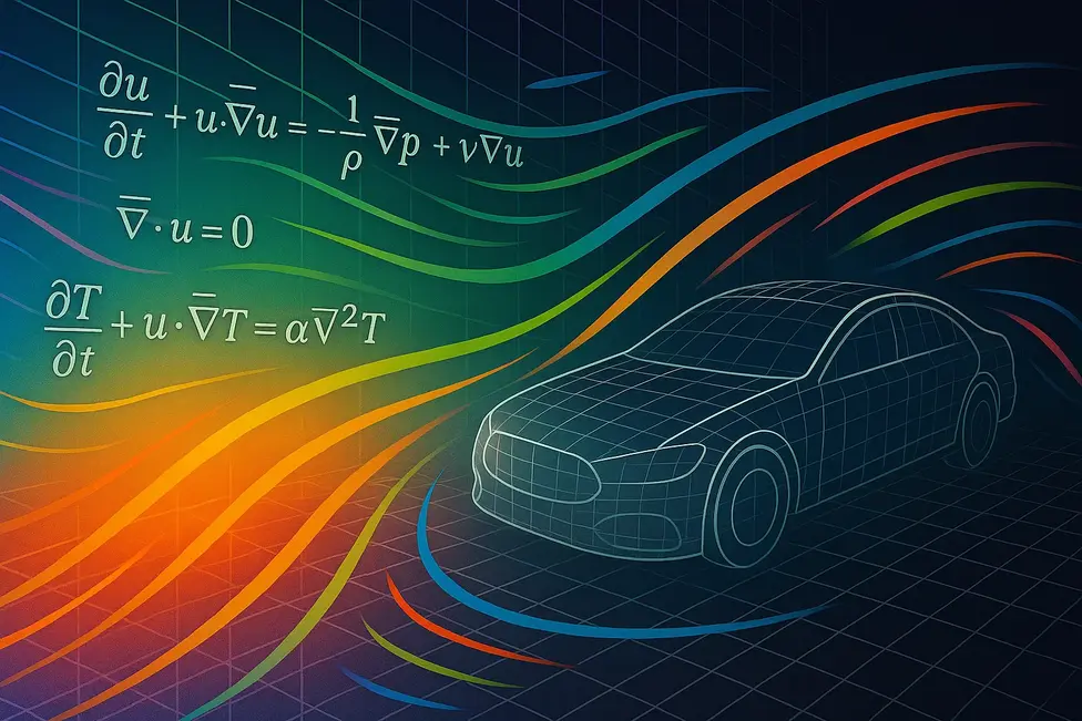
After meshing, the simulation setup is transferred to a CFD solver. This is where the governing equations of fluid motion — based on mass, momentum, and energy conservation — are numerically solved over each mesh cell.
The solver iterates through these equations until the solution converges, providing values for velocity, pressure, and other physical quantities at every point in the flow field.
Different solvers can handle compressible or incompressible flows, laminar or turbulent regimes, and steady or transient conditions.
Step 4: Post-Processing — Visualizing the Results
Once the solver completes, we move to post-processing, where simulation data is transformed into meaningful insights.
Here, engineers visualize flow patterns, identify regions of high drag or lift, and compute engineering quantities like pressure coefficients or velocity contours.
Post-processing bridges the gap between raw numerical data and design decisions, providing the visual clarity needed to optimize shapes, reduce drag, or improve thermal performance.
Bonus: Running the Solver in Cloud Computing Resources
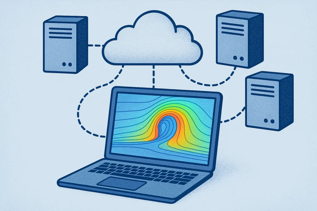
Modern CFD simulations can involve millions of mesh elements and large, time-dependent computations. Running such cases on a personal computer can be slow or even impossible due to hardware limits.
That’s where cloud computing resources come in. By using scalable virtual machines or containerized environments, engineers can run simulations faster and more efficiently — without needing a high-end workstation.
Cloud-based execution allows users to launch, monitor, and manage simulations remotely, often with automatic resource allocation and easy file sharing.
This flexibility not only speeds up project turnaround but also makes CFD more accessible to students, researchers, and professionals working from anywhere.

Bringing It All Together
Each of these steps — from CAD modelling to post-processing — is part of a seamless CFD workflow that transforms ideas into validated designs.
However, for many learners, setting up and integrating all these steps can feel overwhelming, especially when using different tools or platforms. That’s exactly why we created the course.
🎓 Hands-on CFD analysis using open-source tools
This comprehensive course offers a practical introduction to the complete open-source simulation workflow — from 3D modelling to CFD analysis and visualization.
You’ll learn how to:
- Set up and run CFD simulations
- Visualize and analyze results for design decisions
- Compute engineering quantities like lift and drag
- Run simulations efficiently in cloud environments
- Create detailed parametric 3D models
- Generate high-quality computational meshes
- Integrate everything into a reproducible workflow
You need NO PRIOR EXPERIENCE in fluid mechanics or coding — everything is explained clearly from the ground up.
It includes :
- lecture videos
- PDF notes
- and downloadable case files
By the end, you’ll be confident in running your own CFD simulations — from geometry creation to visualization — using open-source tools in a unified workflow.